History of the Sussex Repeater Group
Formed nearly 50 years ago at ‘The Bull’ pub in Ditchling by small group of like-minded amateurs (Mick G4EFO, Andy G8TJQ being among them), the original Sussex Repeater Group built and operated the repeaters listed in Table 1. It eventually became apparent that the responsibility of managing the repeaters with such a small group of people was difficult. Subsequently the group split in two with members along the south coast looking after GB3BR and GB3SR in Brighton while GB3HO, GB3NX and GB3BP were maintained by the remainder in the northern group. The two 23 cm repeaters, GB3WX and GB3CP, were closed. GB3BP (Brantridge Park being the original location of the repeater) had its call sign changed to GB3WS when the call became available
Callsign | Location | Band |
GB3BR | Brighton | 70 cm |
GB3NX | Turners Hill | 70 cm |
GB3SR | Brighton | 2 m |
GB3BP | Worth Abbey | 2 m |
GB3HO | Horsham | 70 cm |
GB3WX | Brighton | 23 cm |
GB3CP | Crawley | 23 cm |
GB3WS | North Sussex | 2 m |
Table 1 The Sussex Repeater Group’s repeaters
The repeater sites
The various locations used for the northern group repeaters are shown in Figures 1 and 2 for the 2 m and 70 cm repeaters respectively. In order of relocation, GB3WS sites (Figure 1) were:
- Worth Abbey
- Marlands
- Kingsfold
- Railtrack site above Balcombe tunnel
- Itchingfield.
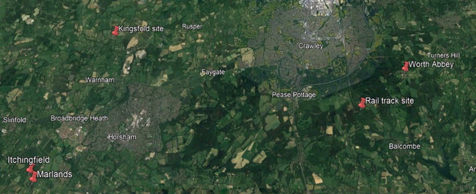
Figure 1 The various sites used for the Sussex Repeater Group’s 2 m repeater, GB3WS
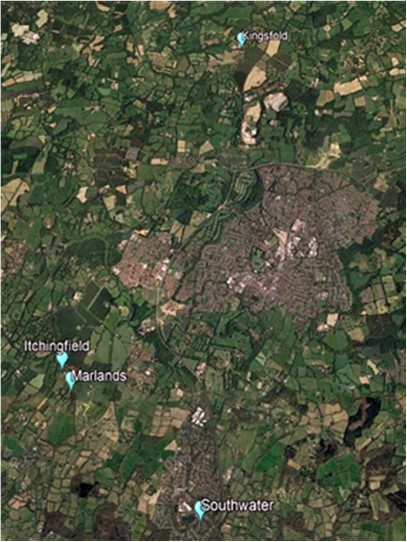
In order of relocation, GB3HO sites (Figure 2) were:
- Southwater
- Marlands
- Kingsfold
- Itchingfield.
Figure 2 The various sites used for the
Sussex Repeater Group’s 70 cm repeater, GB3HO
GB3WS locations 1980-2023
Some very early pictures of the GB3WS and GB3HO tower installation at Kingsfold on the A24 on the Surrey – Sussex border.
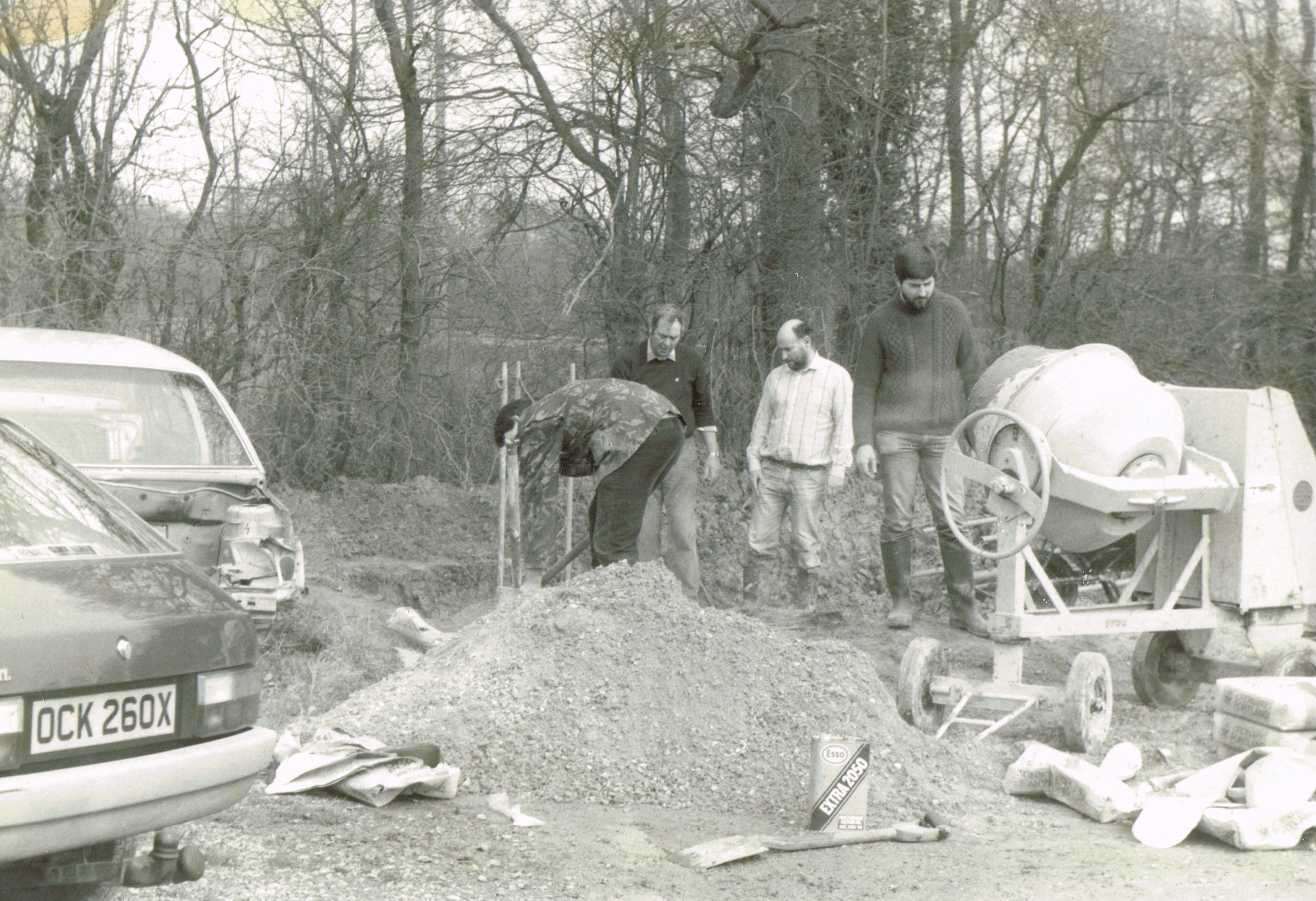
Figure 3 Foundations being dug for the 60′ aerial mast at Kingsfold
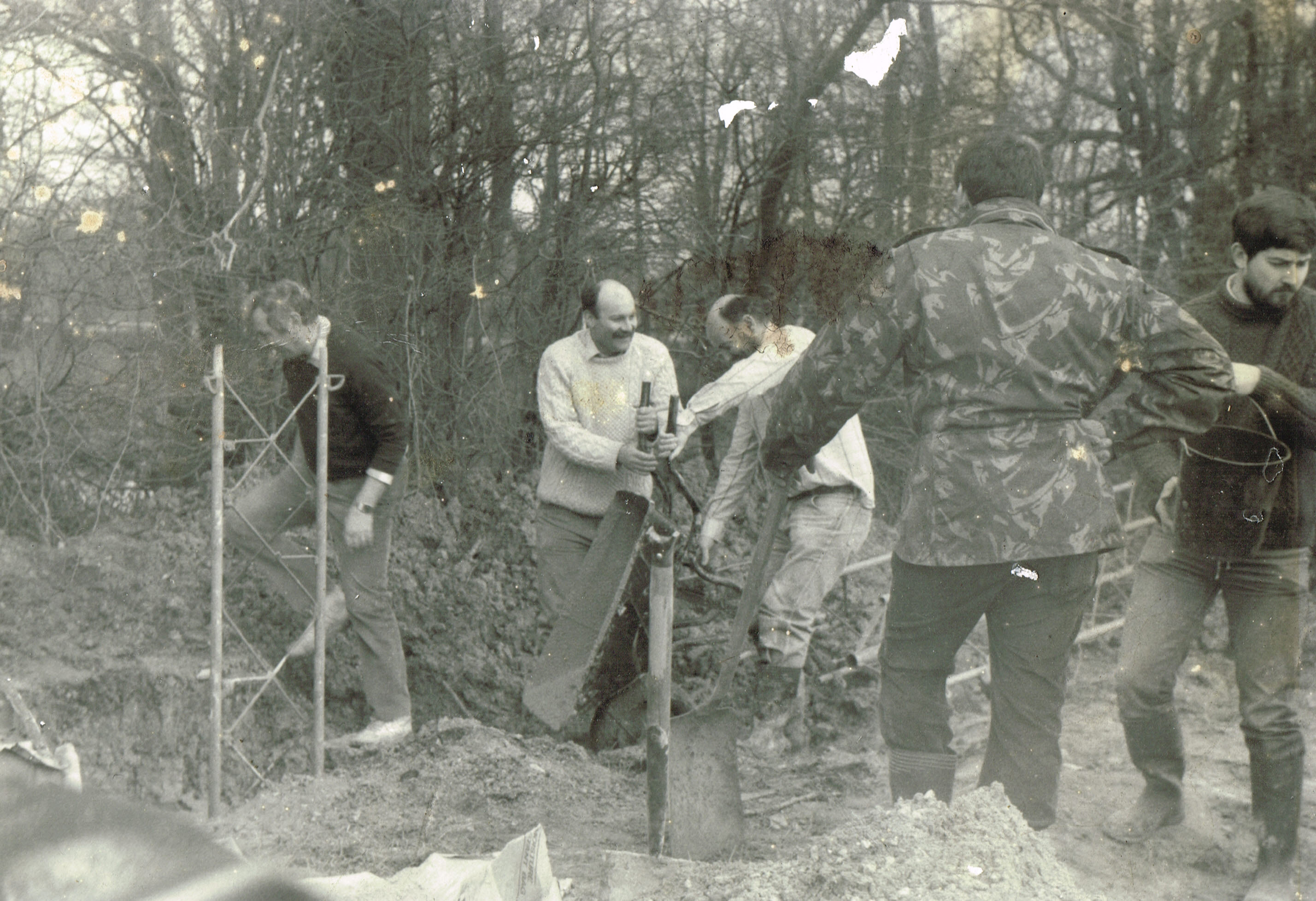
Figure 4 The work carries on, left to right – name? G4EFO G3SWC name? name?
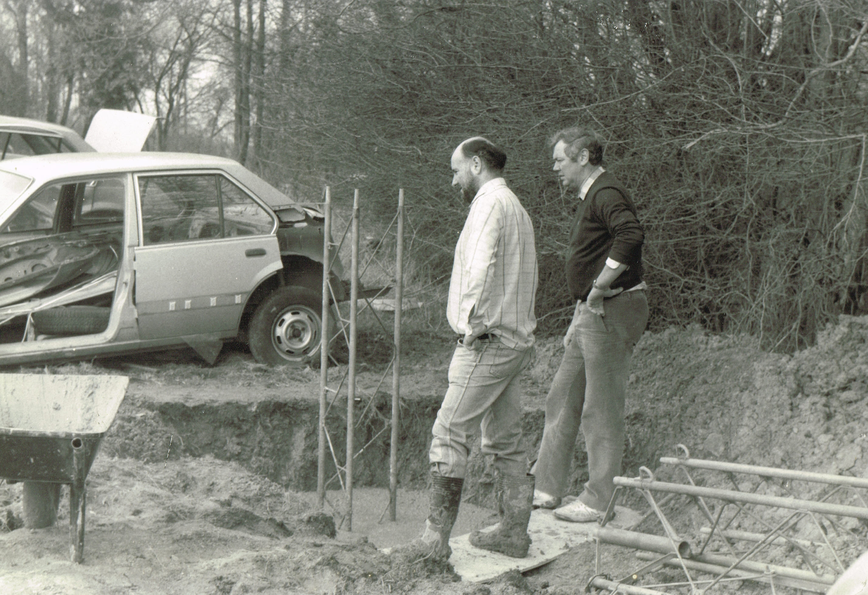
Figure 5 Another couple of shovels should do it !
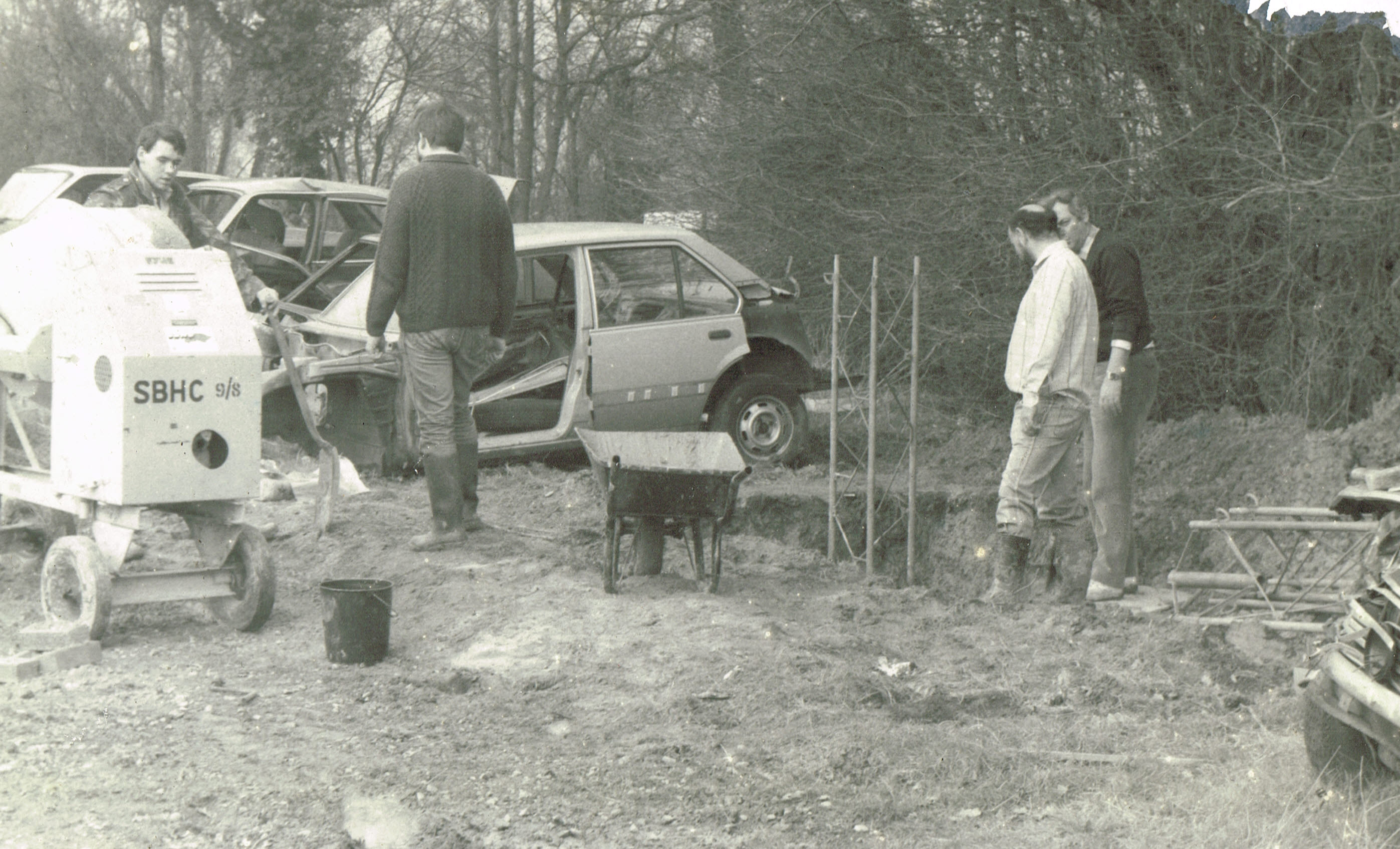
Figure 6 Thats enough for now, down to the pub for refreshment ?
When the mast installation was completed both GB3WS and GB3HO became active from the portacabin (to the right of the mast) from the early 1980’s

Figure 7 So that was the 60ft tower at Kingsford, installed 1983 – destroyed by the hurricane in October 1987 !
Original GB3WS repeater equipment used at Kingsfold.

Figure 8 GB3HO on RB14 and GB3WS R6 at Kingsfold.
From the early sixties we used single channel crystal controlled commercial Storno 6000 series transceivers running 20 watts, which worked very well. Note the big 24 volt power supplies, purchased from GWM radio in Worthing.

Figure 9 This shows the early 2 metre installation, and the start of the change from the air band notch filters to the Sinclair hybrid ring – ( the silver one on the floor )

Figure 10 The original GB3HO repeater on RB14
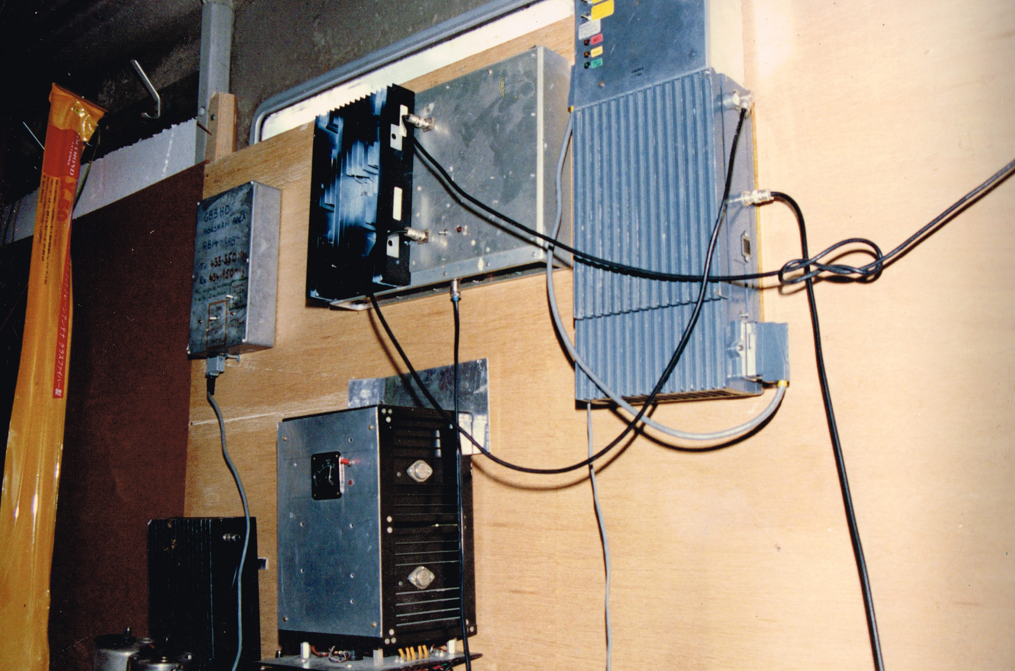
Figure 11 A slightly re-arranged view of GB3WS and GB3HO
GB3WS at the Balcombe Tunnel Railtrack site.
When the mast at Kingsfold was destroyed by the hurricane in October 1987 GB 3HO was closed down and GB3WS moved to new site in the late 1980’s to a Railtrack communications mast above the Balcombe tunnel on the London to Brighton railway line. From this new site, GB3WS used a second hand commercial ICOM IC-RP1510 VHF repeater unit that gave many years of good service.
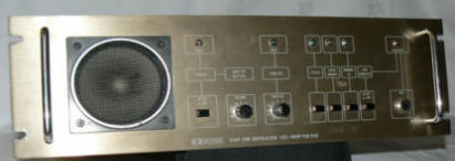
Figure 12 ICOM IC-RP1510 VHF repeater
The GB3WS Aerial System
The picture below shows the now demolished Rail track communications tower which supported the GB3WS antenna system. The repeater antenna is the one at the top of the mast to the left. It was a single folded dipole about 22 meters AGL. The aerial was fed by a 30 meter run of Andrews LDF-450 coaxial cable.
The antenna was spaced one quarter wavelength from the mast with an orientation of 270 degrees. The system was fed via a four cavity Sinclair duplexer, and at the ‘T’ piece was a ferrite circulator.
Each cavity had an insertion loss of about 0.5dB at the wanted frequency and a reject notch in excess of 55dB at the unwanted frequency. There were two cavities in the transmit leg and two in the receive path which allows the repeater to run single aerial working in order to achieve a reciprocal transmit and receive path.
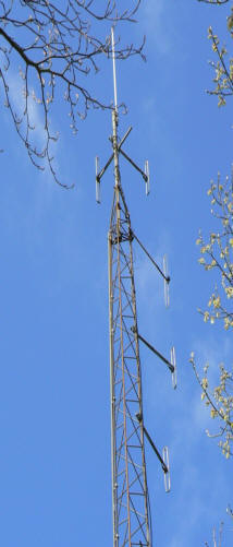
Figure 13 Balcombe Railtrack mast
A new GB3WS
In the early 2000’s the now very old commercial ICOM repeater was changed for a pair of new ICOM IC-F110 transceivers, one for TX and the other RX, and a new external CAT controller (repeater logic). The repeater logic was derived from a CAT300 DX series controller purchased at the Dayton Amateur rally in the U.S.A. from CAT Technology
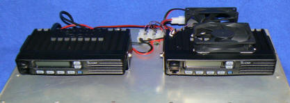
Figure 14 The new IC-F110 transceivers were modified to allow the use of our own external CAT controller and were adjusted to run 25 watts to the input of the duplexer.
GB3WS-Parameters
Operational Parameters for GB3WS pre 2023
GB3WS was the two meter repeater that served an area targeted at the northern part of West Sussex and the South-West parts of Surrey. Because of its geographical location it was very difficult to tailor the aerial pattern, and signals were received across a great deal of northern East Sussex as well as south London.
The repeater used two ICOM IC F110 transceivers that were fed into a 50 watt PA. The PA was set to run at 25 watts. The repeater was then fed via the duplexer to a single dipole antenna approximately 68′ above ground. The coaxial feeder was Andrews LDF4-50.
Single antenna working was achieved by four Sinclair cavities and a phasing arrangement based on a hybrid ring but modified by G4EFO. Each cavity produced a notch of around 55dB at the unwanted frequency, with an insertion loss at the wanted frequency of about 0.5dB
The repeater logic is derived from a CAT300 DX series controller purchased at the Dayton Amateur rally U.S.A. from CAT Technology.
Repeater time out was set at three minutes ( Aug 07 ). Every 15 minutes the repeater will sent a voice ID. On the hour it announces GB3WS and then the time. At 15 minutes past and 15 mins to the hour it gave a female voice ID GB3WS. On the half hour the repeater gave a voice ID followed by the CTCSS sub tone frequency.
Through audio was permitted and a user could continue to use the repeater during an I.D. period. If talk-through is in operation the voice ID was replaced at a convenient break by morse ID, de GB3WS E. ( E being the 88.5hz CTCSS sub tone required to access the repeater). Mick G4EFO made the following comment: “The young lady that gives the occasional “good morning” or “good evening” announcement was a bonus, and I guess she sneaked in as an illegal immigrant. I’ve taken all the covers off the repeater, but alas, I am unable to find her anywhere!”
Access to achieve talk-through required a carrier plus an 88.5 Hz sub audible tone. The repeater also transmitted an 88.5hz CTCSS tone.
The logic had many functions, some of which users will have heard demonstrated, but Mick tried to keep the operation parameters very basic. The logic parameters were easily changeable via the software on a laptop computer and could be loaded onto the repeater in a couple of minutes. By keying up and sending 555 in DTMF tones the repeater would reply with the time.
GB3WS- CAT300 DX Logic
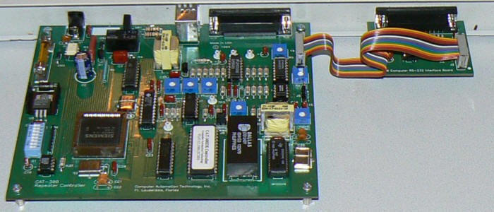
Figure 15 Complete CAT300 DX series controller
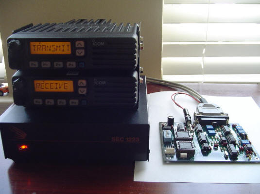
Figure 16 Testing the new GB3WS and its logic

Figure 16 GB3WS in 2023..
This version of GB3WS continued to give good service for the best part of twenty years from the Balcombe Railtrack site until Mick moved it to Itchingfield in early 2023 and co-located it with a re-licenced wide spaced GB3HO on 70cms.
The Railtrack site used by GB3WS
So why was GB3NX closed, and a site move requested for GB3WS? Figure 3 shows the original mast where GB3NX and GB3WS were located. It was a Railtrack mast on one of the air shafts on the Balcombe tunnel on the main London to Brighton line and, although restricted to the West there was extremely good coverage across Sussex and Surrey,
In early 2020 Mick received the news that Railtrack were decommissioning their sites, and Balcombe was one of them. This meant the removal of the tower but in typical EFO style Mick negotiated with them (no doubt over many beers!) and they agreed to leave the base 20-foot section of the mast in situ.
Mick then attached a pole to the top of the 20-foot section and the new antenna was erected at about 30 feet AGL. Unfortunately, this reduction in aerial height drastically reduced coverage and the antenna, now surrounded by tree branches, was frequently suffering from damage.
Figure 17 The tall Railtrack mast at Balcombe used by GB3WS
The G4EFO legacy
Moving forward to early 2023, the Sussex Repeater Group was run and funded solely by Mick G4EFO with a few ‘helpers’ as and when required. Mick started 2023 by closing GB3NX, which had little to no use, he also applied for a site change for GB3WS to Itchingfield. At the same time, he applied for a 70cm DMR license using the callsign GB7WS from his home in Billingshurst.

Figure 18 Michael (Mick) Senior, G4EFO, SK 27th December 2023
GB3WS moves to Itchingfield
In April 2023 Mick moved GB3WS and GB3HO to a farm building in Itchingfield, an excellent “free” location giving solid coverage over the Horsham area.
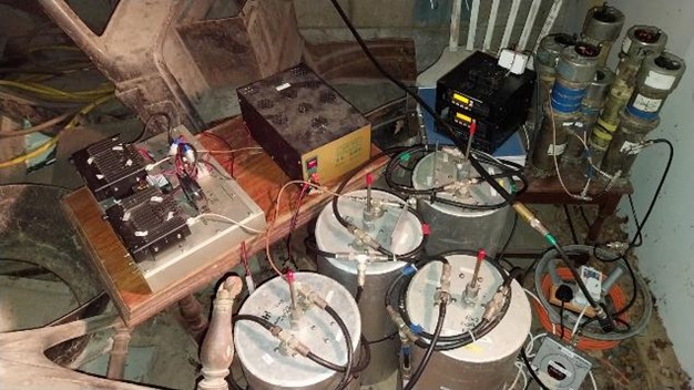
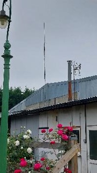
Figure 19 The original ad-hoc repeater set-up at Itchingfield
Figure 20 The original antenna at Itchingfield
GB3HO
The 70 cm repeater, GB3HO is in Itchingfield (just north of Barns Green) and shares a dual band collinear antenna with GB3WS. The RSGB predicted coverage for GB3HO is shown in Figure 8. As can be seen, the repeater provides good coverage for the general area of Horsham as well as the A24 from Dorking to Washington. GB3HO operates on RU71 (TX 430.88750 MHz and RX 438.48750 MHz) and requires CTSS of 88.5 Hz.
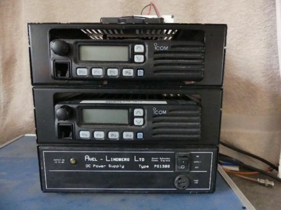
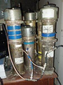
Figure 21 The original equipment and cavity filters used with GB3HO

Figure 22 RSGB predicted coverage for GB3HO
GB3WS pre-2024
GB3WS operates on RV60 (TX 145.750 MHz and RX 145.150 MHz) with 88.5 Hz CTCSS. Figures 9 to 11 show the repeater hardware before its recent upgrade (2024-2025). The RSGB predicted coverage is shown in Figure 12.
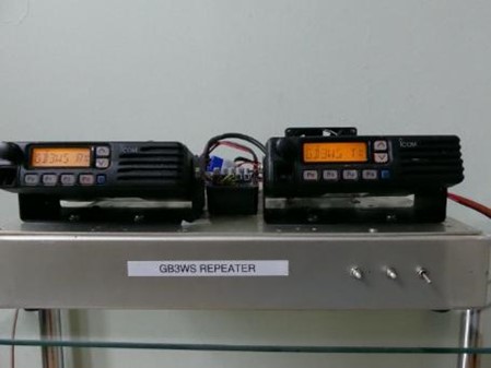
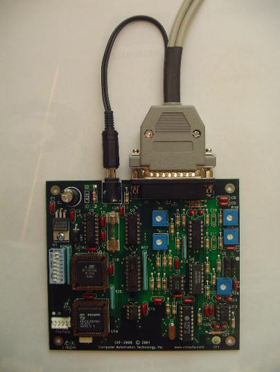
Figure 23 GB3WS TX/RX before the recent upgrade
Figure 24 GB3WS computer interface board
Figure 25 GB3WS control logic
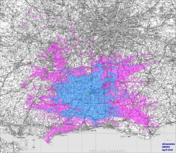
Figure 26 RSGB predicted coverage from the Itchingfield site
GB7WS arrives in Billingshurst
At about the same time, the DMR repeater, GB7WS, entered operation in Billingshurst. The repeater site is to the West of the village and favorably situated with a good take-off in most directions.
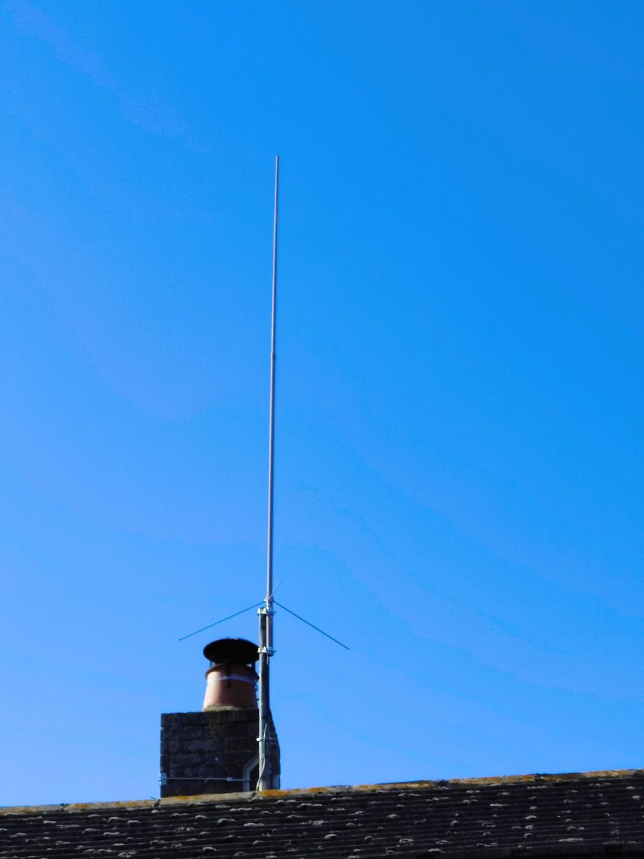
Figure 27 The 70 cm colinear antenna used for the DMR repeater (GB7WS)
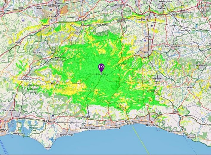
Figure 28 Mobile coverage for the DMR repeater (GB7WS) at Billingshurst
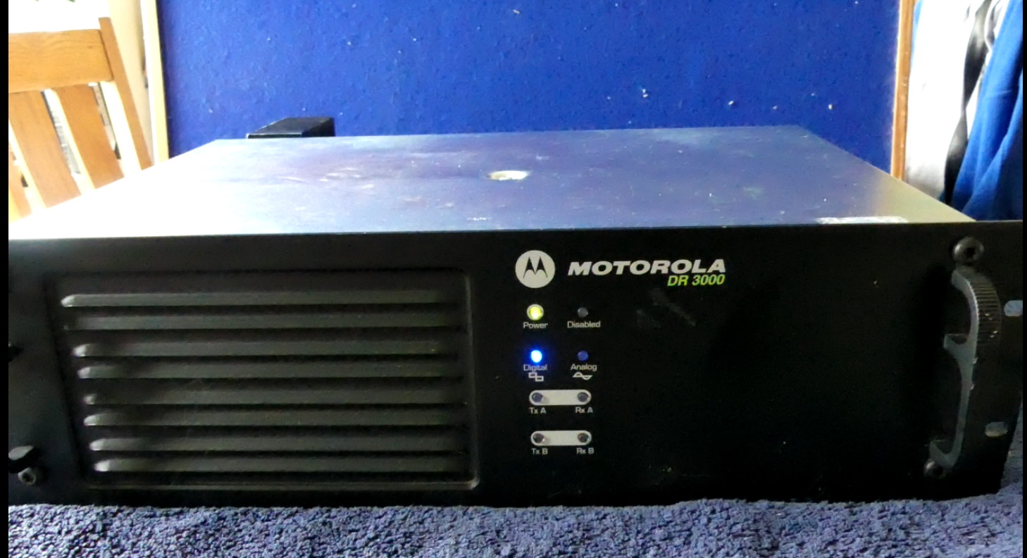
Figure 29 The Motorola DMR repeater at GB7WS in Billingshurst
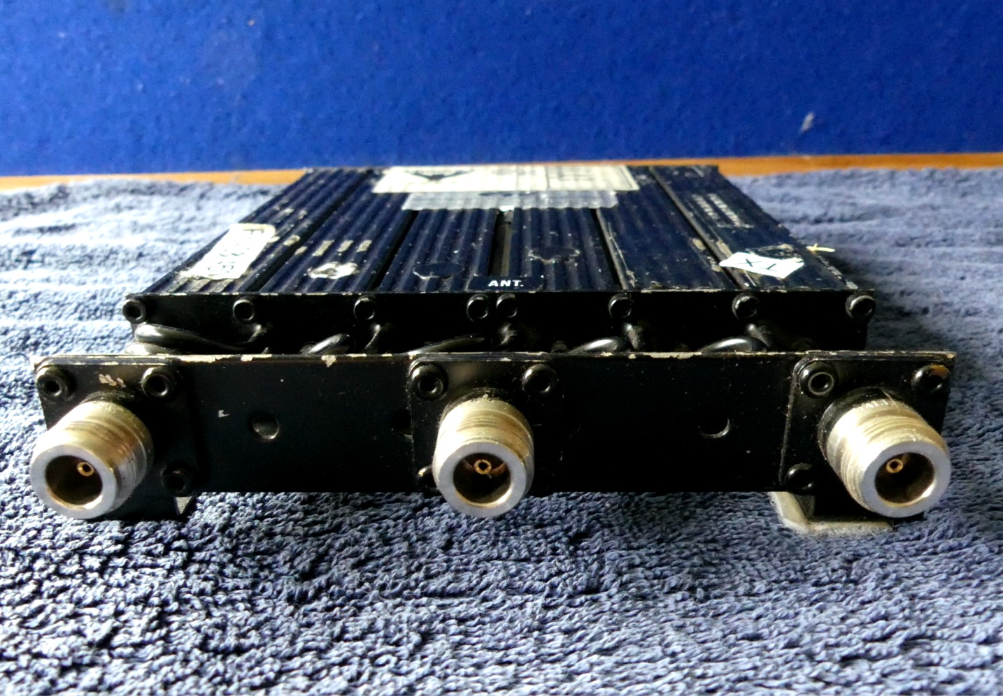
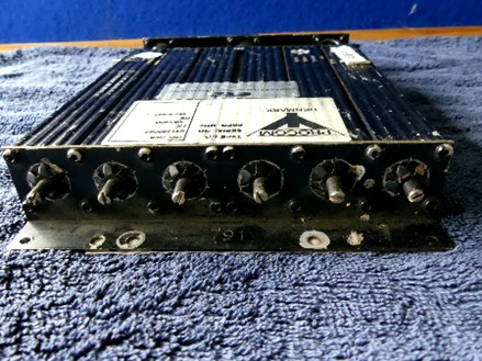
Figure 30 Front and rear views of the cavity duplexer used at GB7WS
The rationale for upgrading
It was always Mick’s intention that the Horsham Amateur Radio Club (HARC) should take over the management and operation of GB3WS, GB3HO and GB7WS. Accordingly, the HARC Chairman, Adrian (G4LRP), now holds the official Notice of Variation (NoV) for each repeater from Ofcom.
Having made numerous visits to the GB3WS and GB3HO repeater site at Itchingfield, it became abundantly clear that the hardware for both repeaters had become “old and tired”, needing more and more ongoing support to keep them operational. It was decided to replace both GB3WS and GB3HO (previously ICOM based repeaters) with Yaesu System Fusion DR-2XE (FM/C4FM) dual-mode repeater units. Both GB3WS and GB3HO became operational on the 11th May 2024 with the two new Yaesu DR-2XE units running 5 Watts
Figure 31 The learning curve begins!
Figure 32 The Yaesu DR-2XE Dual Mode (FM/C4FM) repeaters are easy to program and put into service using the existing cavity duplexer arrangements.
Figure 33 Front -panel view of the two Yaesu repeaters during testing
How does a duplexer work?
A duplexer is a device that allows two-way communication over a single antenna and is normally made up of four to six quarter wavelength coaxial cavities. At the center frequency, the high-Q cavity readily absorbs the energy supplied to it by the input loop.
Then at the output loop the H-field couples back into the transmission line. At resonance very little signal is lost. To the energy on the transmission line, the cavity is invisible. but transparency ONLY happens at the cavity’s resonant frequency. Off resonance, at a higher or lower frequency, the cavity’s impedance rises very rapidly. This greatly suppresses off-frequency signals.
Figure 34 A single high-Q cavity
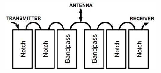
Figure 35 Cavities arranged to allow TX and RX with a common antenna
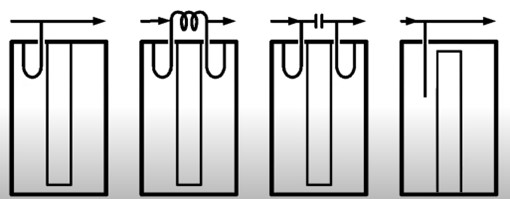
Figure 36 Various coupling methods used with cavities
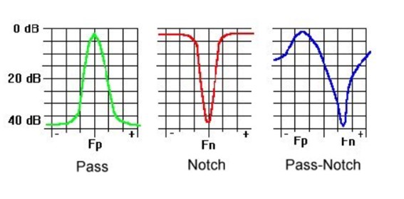
Figure 37 Frequency response of the three types of cavities
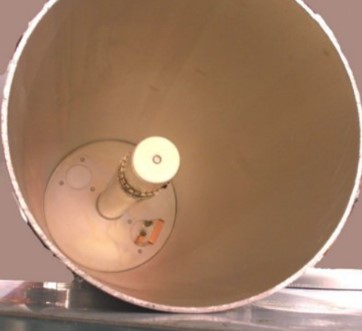
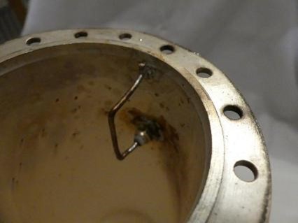
Figure 38 Coupling loops in 2 m and 70 cm cavities
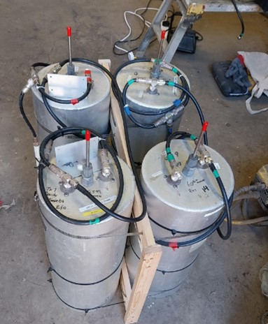
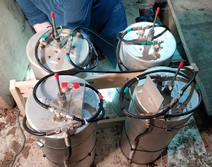
Figure 39 The four cavity filters used on GB3WS
(a) (b)
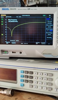
Figure 40 Frequency response of the TX and RX cavity filters used on GB3WS
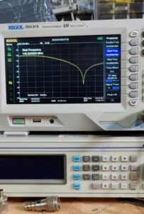
Fig. 40(a) shows the frequency response of the transmit cavity, which notches the receive path. If your eyes are good enough you will see that this is a 60 dB notch, with minimum insertion loss at the wanted frequency.
Fig. 40(b) shows the response of the receive cavity, showing a notch of around 55 dB. So, when a second cavity is added it produces a notch of around 110 dB on the receive side and with the cavities on the transmit side around 120 dB. Adding both together, we achieve around 230 dB of isolation. Note that talk-through isolation is usually achieved with more than 130 dB of isolation.
The response of the cavities that were used for the 70 cm repeater, GB3HO, is shown in Figures 41 and 42.
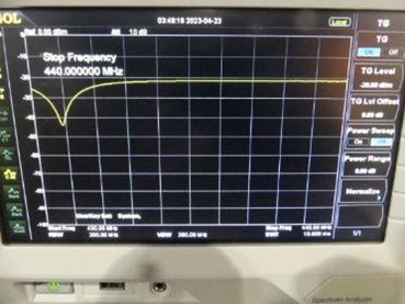
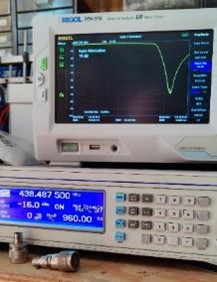
Figure 41 Response curve of a single 70cm cavity
Figure 42 Response curve of three 70cm cavities
70cm duplexers now used for GB3HO and GB7WS
With wide spaced 70cm repeaters (7.6MHz) now being the norm instead of the older 1.6MHz spaced repeaters a compact commercial repeater duplexer allows for a simpler repeater installation avoiding the need for individual cavities connected by ¼ wave coax lines. Figures 29 and 30 respectively shows the Procom duplexer and its frequency response.

Figure 43 The Procom duplexer

Figure 44 Duplexer frequency response (the TX response is indicated by the yellow trace while the RX response is shown by the red trace)
What is a circulator and how does it work?
A circulator is a three-port passive electronic device used in RF communication systems, radar, and microwave circuits. Its primary function is to control the direction of signal flow. Essentially, it routes an incoming RF signal from one port to the next in a clockwise or counterclockwise manner, while isolating it from the previous port.
Here’s a quick breakdown of how it works:
Ports: The device has three ports (sometimes more in some equipment). If a signal enters Port 1, it will be directed to Port 2, and if it enters Port 2, it will flow to Port 3. Likewise, a signal entering Port 3 will flow to Port 1. In Figure 29 the RX is connected to Port 1, the TX to Port 2 and the Antenna to Port 3, and the red arrows in Figure 30 indicate the direction of power flow through the device.
Magnetic Material: The core of an RF circulator often uses a magnetized ferrite material. The magnetic properties of this ferrite create non-reciprocal behavior, which means the signal only flows in one designated direction around the ports.
Applications: In a TX-RX system (such as a repeater) the circulator can separate the outgoing signal (from the transmitter) and the incoming signal (from the antenna) to avoid interference. They are also used in duplexer circuits, radar systems, and test setups where a high degree of isolation between different parts of a circuit is needed. This isolation between ports minimizes losses and enhances system performance.
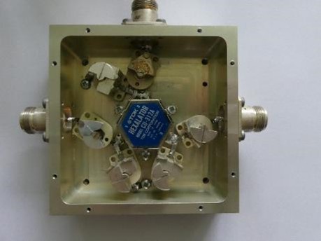
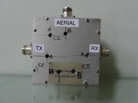
Figure 45 The GB3WS circulator
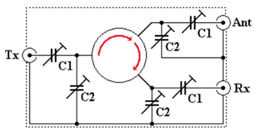
Figure 46 The GB3WS circulator is based on a TDK Hexalator
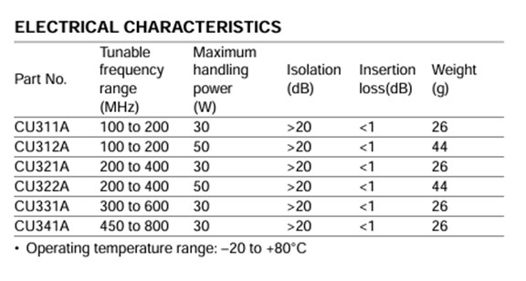
Table 2 Specifications for the TDK Hexalator (a trade name used by TDK for a non-reciprocal device composed of microwave ferrites, mesh-like centre conductors and a permanent magnet).
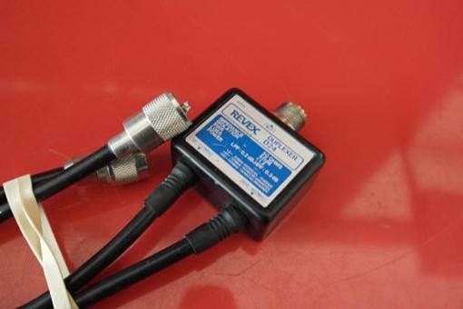
Finaly both repeaters are then combined by a Revex D24 Duplexer 1.6-150 – 400 460 MHz combines both repeaters onto the single LDF450 feeder to the Diamond X-200 dual band antenna.
Repeater configuration
The configuration of GB3WS and GB3HO is shown in Figure 32. Note the four individual cavity filters used on 2 m and the six-cavity filter pack used on 70 cm. The circulator and diplexers (see earlier) are also shown.
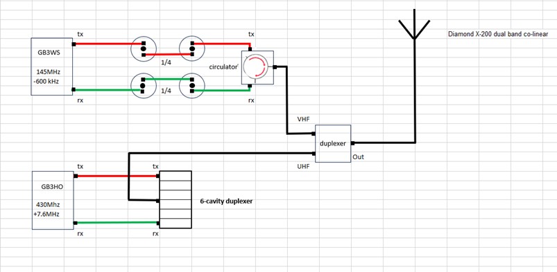
Figure 47 Configuration of GB3WS and GB3HO
Repeater specifications
GB3WS
Repeater TX o/p 7 dBW (5 W)
Cavity loss -0.5 Dbw
Circulator loss -0.1 dBW
Duplexer loss -0.1 d BW
Feeder (LDF450) loss -0.3 dBW
Antenna gain 6 dB
Output ERP 12 dBW (16 W)
GB7WS (DMR)
Repeater TX o/p 10 dBW (10 W)
Cavity pack loss -1.4 dBW
Feeder (RG213) loss -2 dBW
Antenna gain 6 dB
Output ERP 12.6 dBW (18 W)
GB3HO
Repeater TX o/p 7 dBW (5 W)
Cavity pack loss -1.4 dBW
Duplexer loss -0.1 dBW
Feeder (LDF450) loss -1.2 dBW
Antenna gain 8 dB
Output ERP 12.3 dBW (17 W)
What happened next?
Here’s a brief photographic record of tasks carried out during the repeater upgrading:
1st July 2024: Site survey and planning
A site survey was carried out for the installation of a Swedish ex-military telescopic mast and aerial system for GB3WS and GB3HO. To provide improved and more consistent coverage, the repeater antenna was moved to the northwest corner of the building. However, the mast had first to be recovered from undergrowth and fully tested before this work could be carried out. We also had to agree the installation plan with the site owner.
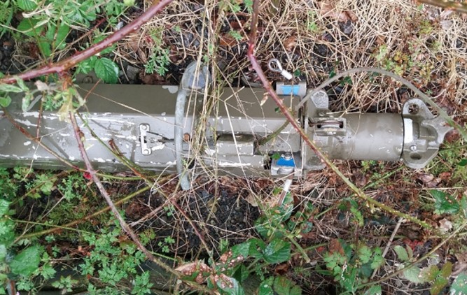
Figure 48 Spot the mast? The telescopic mast (almost) buried in the undergrowth
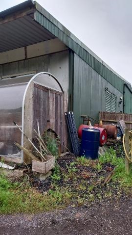
Figure 49 Corner of the farm building where the mast was to be erected
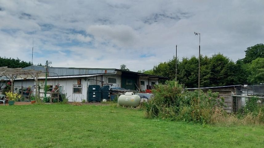
Figure 50 A general site view showing the original antenna (left)
together with the new telescopic antenna mast (right of centre)
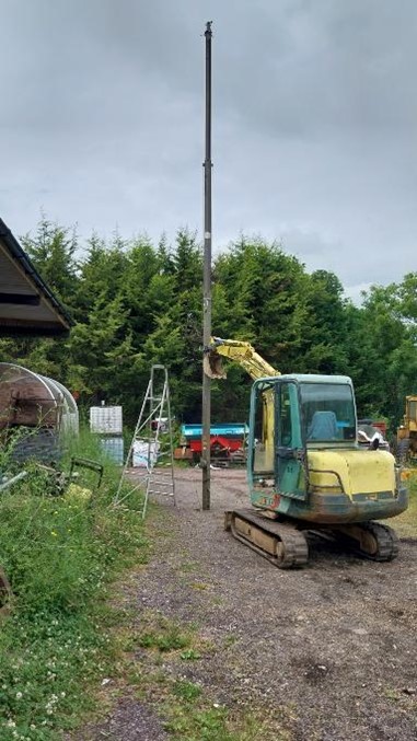
Figure 51 Using a digger to support the mast during initial testing
24th September 2024: Mast brackets built and fitted
Mast support brackets were cut from scrapped chassis/frame, then welded to vertical barn I-beam. Many thanks to our site owner, Peter!

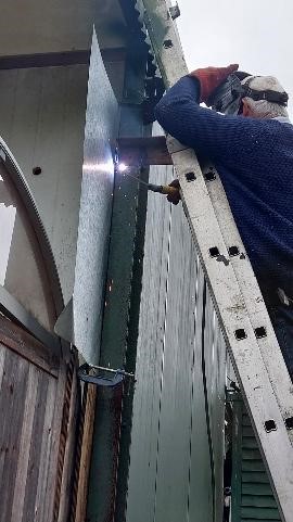
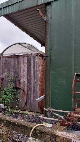
Figure 52 Manufacturing and fitting the mast brackets
17th October 2024: Mast installed and tested
The next stage involved installing the mast using the nwely fitted brackets and a substantial U-bolt arrangement.
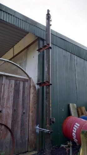
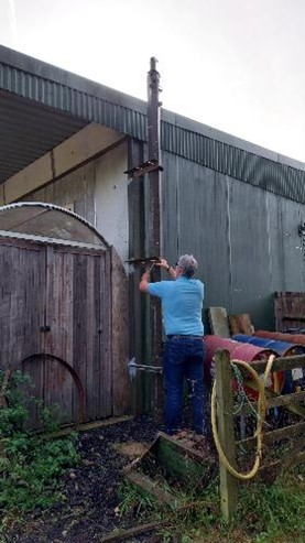
Figure 53 Mast retracted (left) while Gavin, G7DFV, makes final
adjustments to the rubber-lined U-bolt clamps
13th November 2024: Antennas fitted and tested
Later in November, the Diamond X-200 dual-band antenna with new LDF450 coaxial feeder were installed on the mast.
The antenna specifications were as follows:
Band: 2 m/70 cm
Gain (dB): 6.0/8.0
Max Power Rating: 200 W
Wind Rating: 112 mph
Height (feet): 8.3
Connector: N-Type
Element Phasing: 2 x 5/8 wavelength, 4 x 5/8 wavelength
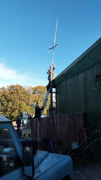
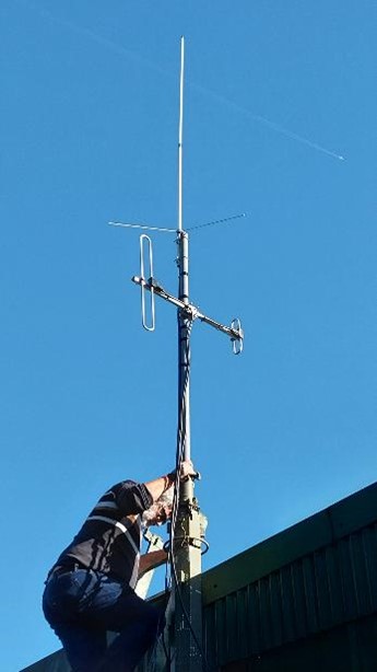
Figure 54 Final attachment of the antenna system. G7DFV at the top of the ladder!
10th December 2024: GB3HO moved to the new location and tested with the new antenna
GB3HO was moved onto the new antenna and 70 cm coverage became much improved. The move for GB3WS (and its ultimate combination with GB3HO) was deferred until the following spring when better weather could be expected.
18th March 2025: GB3WS moved to its new location
GB3WS was moved from its old location on the eastern side of the barn to its new location on the northwest corner of the barn. The repeater equipment was also installed into a new equipment cabinet along with GB3HO. Both repeaters now have a UPS back up and share the Diamond X-200 dual band co-linear on top of the mast (approximately 45 ft above ground level). As a result, both repeaters are showing improved performance in Horsham and the surrounding area.
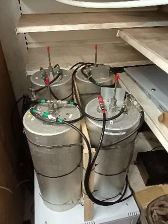
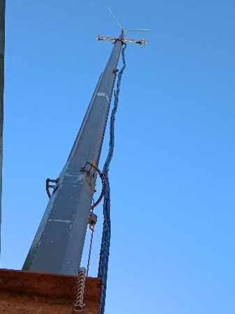
Figure 55 The completed upgrading of GB3WS and GB3HO

Figure 56 The new arrangement of the repeater hardware (compare with Figure 5!)
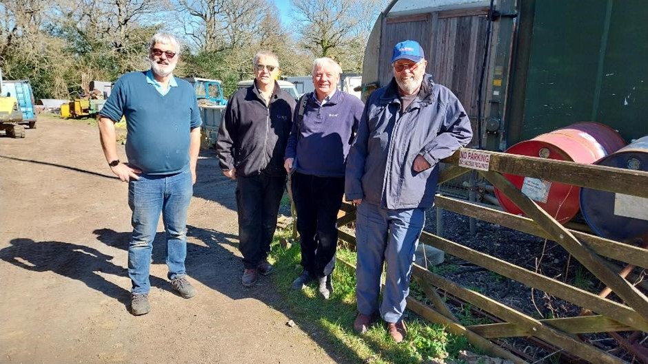
Figure 57 Time for a pint? HARC “volunteers” take a break
(from left to right; G7DFV, G8TJQ, G8CKT, G3OGP)
Footnote:
HARC currently has no plans for internet linking of the two C4FM repeaters. The DMR repeater, GB7WS, is already internet linked and, for members in the Horsham area, the new public node (MB6HS) provides a means of connecting to the Wires-X network. The node operates on 144.8125MHz and has been kindly provided by Raffaele, M0JLZ.